
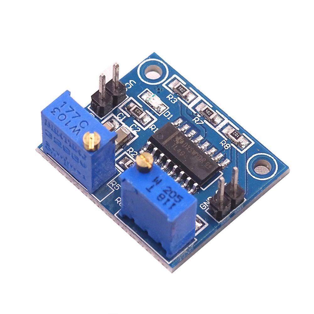
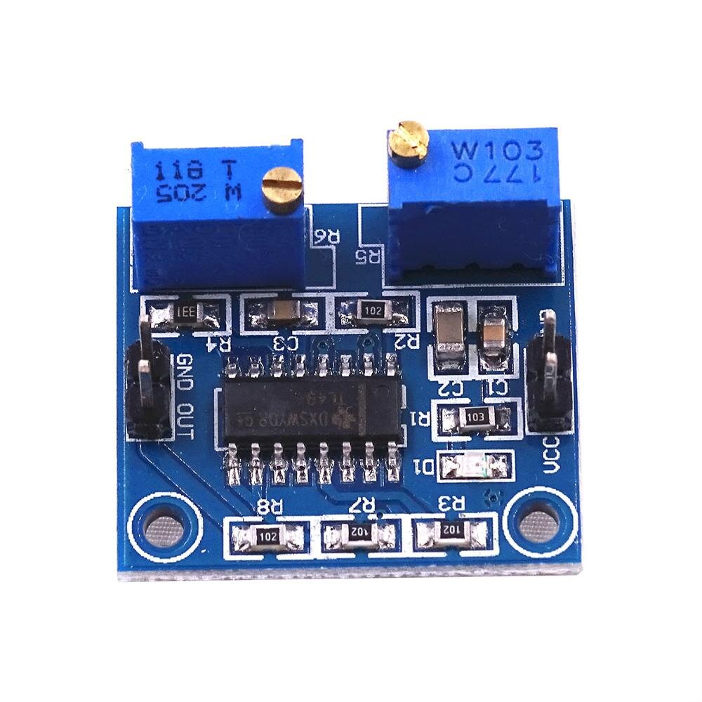
TL494 PWM Controller Module is a high-performance integrated circuit (IC) mounted on a compact breakout board, designed to simplify the creation of efficient switching power supplies, DC-DC converters, and motor control circuits. At the heart of this module is the industry-standard TL494 chip, which integrates all the necessary functions for a pulse-width modulation (PWM) control circuit. It features two error amplifiers, an internal reference voltage, an oscillator, and a dead-time control comparator. Engineers and DIY enthusiasts choose this module because it offers a ready-to-use solution for driving power FETs and transistors with precisely controlled duty cycles and frequencies, enabling robust and predictable power management designs.
Key Features:
- Integrated PWM Control: Utilizes the powerful TL494 IC to provide precise and stable control over the duty cycle of switching elements.
- Adjustable Output Frequency: You can easily set the oscillator frequency using an external resistor and capacitor, offering maximum design flexibility.
- Dual Error Amplifiers: The two internal error amplifiers allow for simultaneous voltage and current feedback loops, enhancing regulation accuracy.
- Dead-Time Control: A built-in dead-time control comparator gives you the ability to prevent simultaneous conduction of output transistors, which is crucial for full-bridge and half-bridge topologies.
- Output Control: The output control pin allows you to select single-ended or push-pull operation, adapting the module to various circuit needs.
- 5V Reference Output: Provides a stable 5V reference voltage (VREF) output for external circuit use, simplifying sensor and feedback network design.
Technical Specifications:
- Controller IC: TL494
- Supply Voltage (VCC): 7 V to 40 V
- Output Voltage (VC): Up to 40 V
- Reference Voltage Output (VREF): 5.0 V ±5%
- Maximum Output Current (IO): 200 mA (Sink or Source)
- Oscillator Frequency Range: 1 kHz to 300 kHz
- Output Type: Push-Pull or Single-Ended
- Onboard Components: LED power indicator, terminals for external R and C for frequency adjustment.
Mechanical Specifications:
- Module Type: Breakout PCB for the DIP-16 TL494 IC.
- Connectors: Screw terminals for secure power and output connections; pin headers for control/feedback signals.
- Mounting Holes: Two mounting holes for easy installation into enclosures.
Dimensions:
- Board Length: ~35 mm
- Board Width: ~30 mm
- Board Height: ~15 mm (including screw terminals)
Pinout and Wiring:
- VCC: Power supply input (7V to 40V).
- GND: Ground connection.
- OUT1 / OUT2 (C1 / C2): Collector outputs for the two internal transistors. Use these to drive external power stages.
- E1 / E2: Emitter outputs for the two internal transistors (typically connected to GND in single-ended mode).
- VREF: Stable 5V Reference Output.
- RT / CT: Pins for connecting the external resistor (RT) and capacitor (CT) to set the oscillator frequency.
- DT: Dead-Time Control pin.
- EAFB / EAIN: Non-inverting (+) and Inverting (-) inputs for Error Amplifier 1 (used for voltage regulation).
- Wiring Note: Connect VCC and GND first. Then, select your desired output frequency using the RT/CT terminals. Use the error amplifier inputs to feed back your output voltage or current signal for closed-loop regulation.
Datasheet Reference:
Commonly Used in:
- Power Supply Development: The standard IC for building custom desktop computer power supplies and regulated battery chargers.
- Inverters and Converters: Essential in designing push-pull, full-bridge, or half-bridge DC-DC converters and small power inverters.
- Industrial Control: Used in isolated power delivery stages for industrial machinery and electronic equipment.
Applications:
- Regulated Switching Power Supplies: Build high-efficiency, regulated outputs for sensitive electronics.
- Battery Charging Systems: Precisely control charging current and voltage for Li-ion, lead-acid, or NiMH batteries.
- DC Motor Speed Control: Use the PWM output to vary the effective voltage to DC motors, controlling their speed and torque.
- High-Frequency Signal Generation: Create square wave signals for testing and driver circuits.
Equivalent Models:
- SG3525: A popular PWM controller IC, often favored for its built-in soft-start capability and high current output drivers.
- UC384x Series (e.g., UC3842): Current-mode PWM controllers commonly used for flyback and boost converter topologies.
Package Includes:
- 1 x TL494 PWM Controller Module
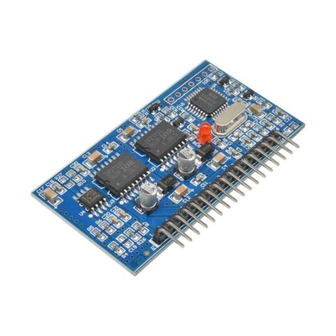 EGS002 EG8010 IR2110 DC-AC SPWM Pure Sine Wave Inverter Driver Module
Reviews
No reviews yet. Be the first to share your experience!